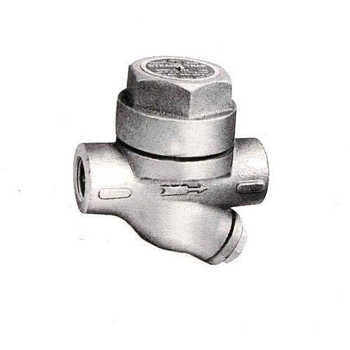
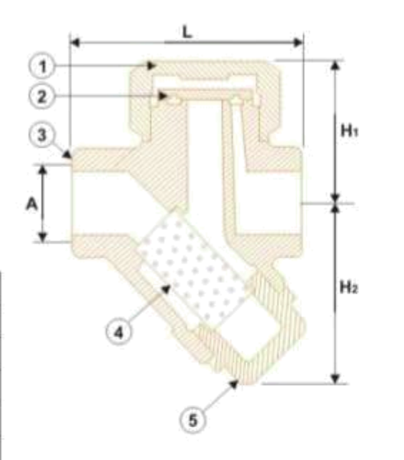
Stainless Steel Steam Trap
Features | SS Steam Trap
- Inbuild Stainer: Avoids Clogging
- Screwed Female BSP Taper Ends/ Socket Welded Ends
- Hardened disc to withstand continuous water hammering
- All Stainless Steel Construction : Better Mechanical Properties
- Integral With Body : No Possibility Of Leakage From Joints
Operation | SS Steam Trap
The steam trap works on the pressure difference, above and below the disc. Disc is rased from its seat due to incoming pressure. High velocity of flashing condensate create low pressure beneath the disc. At the same time pressure is build up in the chamber that force the disc on the seat. Now the condensates in the chamber decrease the pressure, when it is lower than the inlet pressure, the disc lifts. This cycle repeats again and again.
Materials of Construction | SS Steam Trap
| Name of part | Material | Standard |
|---|---|---|
| 1. Top Cover | Cast Stainless Steel | ASTM-A 743 Gr. CA 40 |
| 2. Disc | Cast Stainless Steel | ASTM-A 743 Gr. CA 40 |
| 3. Body | Cast Stainless Steel | ASTM-A 743 Gr. CA 40 |
| 4. Screen | Stainless Steel | AISI - 304 |
| 5. Bottom cover | Cast Stainless Steel | ASTM-A 743 Gr. CA 40 |
Limiting Conditions
- In accordance to ISO 6552
- Body design conditions PN 63
- Cold Hyd. pressure 95 Bar
- PMA - Maximum Allowable Pressure 63 Bar
- PM0 - Maximum Oparating Pressure 42 Bar
- TMA - Maximum Allowable Temperature 400* C
- TMO- Maximum Oparating Temperature 255* C
Sizes/ Dimentions
| Sizes | Dimentions | ||||
|---|---|---|---|---|---|
| Inches | mm | A | L | H1 | H2 |
| 1/2" | 15 | 1/2" BSP | 78 | 44 | 60 |
| 3/4" | 20 | 3/4" BSP | 78 | 44 | 60 |
| 1" | 25 | 1" BSP | 74 | 54 | 70 |
| 1.1/2" | 40 | 1.1/2" BSP | 108 | 70 | 88 |
| 2" | 50 | 2" BSP | 108 | 70 | 88 |
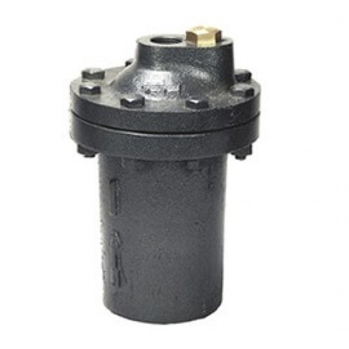
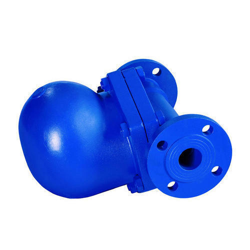
Cast Iron Inverted Bucket Type Steam Trap
Features
- Inverted Bucket Type Steam Trap
- Stainless Steel AISI 304 Bucket
- Renewable Stainless working parts
- Screwed Female Ends to BS 21 / NPT
| Sizes | Dimentions | |||
|---|---|---|---|---|
| Inches | mm | A | H | D |
| 1/2" | 15 | 1/2" BSP | 168 | 142 |
| 3/4" | 20 | 3/4" BSP | 200 | 142 |
| 1" | 25 | 1" BSP | 268 | 186 |
| 1.1/2" | 40 | 1.1/2" BSP | 395 | 238 |
| 2" | 50 | 2" BSP | 452 | 286 |
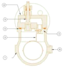
Materials of Construction
| Name of part | Material | Standard |
|---|---|---|
| 1. Plug | Bronze | BS: 1982 491K |
| 2. Cover | Cast Iron | BS 1561 GJL-250 (GG25) |
| 3. Valve seat | Stainless Steel | ASTM A276 Type 410 |
| 4. Fastners | Alloy Steel | |
| 5. Gasket | Non Asbestos Fiber |
PMO - Maximum Operating Pressure - 17.5 bar
TMA - Maximum Allowable Temperature 220*c
Materials of Construction
| Name of part | Material | Standard |
|---|---|---|
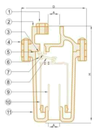
| 6. Hook | Stainless Steel | AISI 304 |
| 7. Ball Seat | Stainless Steel | AISI 410 |
| 8. Lever | Stainless Steel | AISI 304 |
| 9. pipe | G.I. | |
| 10. Bucket | Stainless Steel | AISI - 304 |
| 11. Body | Cast Iron | BS 1561 GJL-250 (GG25) |
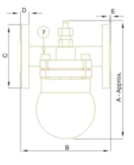
Ball Float Steam Trap (Flanged/Screwed)
Features
- Screwed Female Ends to BS 21/NPT [Screwed version]
- Flanged Ends to PN 16 RFT [Flanged version]
- All Stainless Steel working parts
- With Steam Lock Release (SLR) Assembly
- Painted with Heat Resistent Paint (upto 400*c)
- Drain plug provided for removal of impurities
Description
Ball Float Steam Trap is meant for timely removal of condensate from the pipeline without compromising on the energy losses. It's a mechanical steam trap which works on the principle of difference between densities of steam and condensate.
Materials of Construction
| Name of part | Material | Standard |
|---|---|---|
| 1. Body | D.I./SGI | GGG-40 |
| 2. Float Assembly | Stainless Steel | AISI 304 |
| 3. Valve Seat | Stainless Steel | ASTM A276 Type 410 |
| 4. Gasket | Non Asbestos | |
| 5. SLR unit | Stainless Steel | AISI 304 | 6. Cover | D.I./SGI | GGG-40/td> |
| 7. Fastners | Alloy Steel/td> | ASTM 193 B&/A194 2H |
| 8. Drain Plug | Stainless Steel | ASTM-A 743 Gr. CA 40 |
Limiting Conditions
- In accordance to ISO 6552
- Body design conditions PN 16
- Cold Hyd. pressure 24 Bar g
- PMA - Maximum Allowable Pressure 16 Bar
- TMA - Maximum Allowable Temperature 250* C
Sizes/ Dimentions
| Sizes | A | B | C | D | E |
|---|---|---|---|---|---|
| DN 15 | 195 | 150 | 95 | 14 | 2 |
| DN 20 | 195 | 150 | 105 | 16 | 2 |
| DN 25 | 220 | 160 | 105 | 16 | 2 |